Optimal yaw offset
The optimal yaw offset is the yaw misalignment that maximises the power output of a turbine. A yaw recalibration should target this value rather than zero. Tipspeed estimates it per turbine from SCADA data only.
Typical use: set the target of a yaw recalibration, checked against the satellite-based misalignment estimate.
Yaw misalignment estimation measures the orientation of the rotor relative to the wind. It does not determine the orientation that maximises power. The direction that maximises the power of a turbine can differ from the hub-height wind direction, for the following reasons:
- wind shear, inclined flow and wind veer across the rotor mean that the inflow is not uniform over the rotor, so the orientation of maximum power is not necessarily the one facing the hub-height wind;
- wakes from upstream turbines shift the optimum further;
- the rotor rotates in one direction, so a misalignment to the left of the wind does not have the same effect on loads and power as the same angle to the right.
Method
The optimal yaw offset is estimated per turbine, from SCADA data only, in four steps.
- Operating window. Only full-performance records between 20% and 80% of the rated power of the turbine are used. Above this band, the turbine is power-limited and its output no longer responds to yaw, so misaligned and aligned records cannot be distinguished. Below it, the yaw effect is masked by measurement noise.
- Reference power. The power of a turbine varies far more with the wind than with its yaw. The effect of the wind is therefore removed before the effect of yaw is evaluated. Neighbouring turbines are selected as references: the nearest turbines first, then those whose power correlates most closely with the target turbine. A gradient-boosted regression predicts the power of the target turbine from the power, nacelle wind speed, blade pitch, rotor speed and orientation of the reference turbines. The ratio of measured to expected power represents the behaviour of the target turbine, with the shared wind resource divided out.
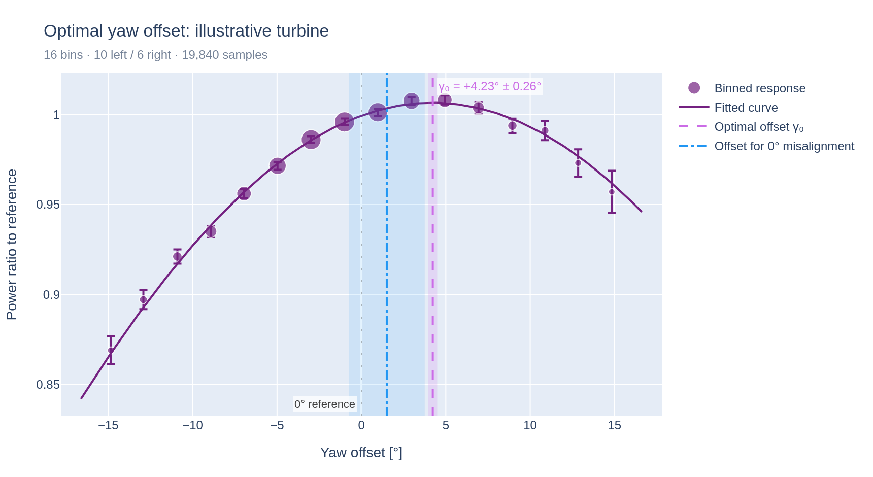
- Binning. The power ratio is averaged in bins of measured misalignment. Each bin keeps its standard error, so that the fit gives more weight to well-populated bins than to sparse ones. Two binning schemes are computed: one with a fixed bin width and one with an equal sample count per bin. The two schemes are not averaged. They are compared, and a material disagreement between them is reported as a caveat.
- Fit. A cosine response is fitted to the bin means by weighted least squares. Power decreases as the cosine of the angle from an unknown optimum, raised to an exponent that is also fitted, because the power of operating turbines decreases faster than a plain cosine. The location of the peak is the optimal yaw offset. Its uncertainty is derived from the fit covariance.
Fit outcomes
Each fit has one of three outcomes:
- The fitted curve is bracketed by observations on both sides. The peak of the curve is the optimal yaw offset and is reported as a measurement.
- The peak lies outside the measured range, or close to its edge. The binned response is searched for a discrete peak on the same side of zero as the fitted optimum, that is, a bin whose mean is higher than the means of both adjacent bins. If such a peak exists, the highest one is reported. It carries the uncertainty of the rejected fit. The fitted curve is not drawn, because the value results from a discrete selection rather than a continuous fit.
- No discrete peak exists. No optimal yaw offset is reported. The fitted value is drawn in grey, for reference only, and labelled as not supported by a valid fit.
Less severe issues are reported with the value instead of suppressing it, so that its reliability can be assessed:
- a wide confidence interval;
- a disagreement between the two binning schemes;
- a curve shape at the limit of its range.
Comparison with the zero-misalignment offset
The offset that would bring the mean misalignment of the turbine to zero is drawn alongside the fitted optimum, so that the two candidate corrections can be compared directly. This offset is shown with a band of ±2.25°, the mean absolute error of the misalignment estimate, because it is derived from an estimate rather than from an exact angle.
Limitations
The optimal yaw offset has limitations, and its reliability depends on the turbine technology. It is an indicative metric rather than a definitive assessment. It need not agree with the yaw misalignment derived from satellite observations, which does not depend on turbine technology. When the two estimates agree, in particular in direction, they corroborate each other and the conclusion is more robust. When they disagree, both should be interpreted with more caution.