Yaw misalignment estimation without lidar
Yaw misalignment is the angle between the direction a wind turbine's rotor faces and the wind direction. Tipspeed estimates it for every turbine without additional sensors, by combining high-resolution satellite imagery with a numerical weather model. Across 23 blind tests against nacelle-mounted lidar, the mean absolute error was 2.25°.
Typical use: identify the turbines that need a yaw recalibration, target a lidar campaign on the most affected ones, and check each correction over time.
Yaw misalignment, the average difference between the orientation of the rotor and the wind direction, causes underperformance. Existing evaluation techniques have the following limitations:
- external sensors such as lidar are highly accurate but difficult to deploy at scale;
- the performance of SCADA-based analytics varies between turbine types and sites, and depends strongly on input data quality.
The Tipspeed method requires no additional sensor. It improves on data-driven techniques by combining high-resolution satellite imagery with numerical weather models (Tipspeed, 2025b). For each turbine, the yaw misalignment time series is the difference between:
- the nacelle direction, corrected for the North offset;
- the wind direction, corrected by the wind flow model and the wake model.
Validation against nacelle lidar
The method was validated in 23 blind tests with several customers, on seven sites across two continents, covering varied terrain complexity and turbine models. All turbines had previously been tested with a nacelle-mounted lidar. The lidar results were disclosed only after Tipspeed had produced its estimates. The first results were presented in (Tipspeed, 2025b); the validation has been extended since.
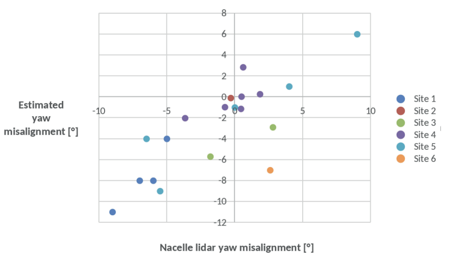
The results show a good correlation with lidar and a mean absolute error of 2.25°. One site showed a larger deviation, which is under investigation. On two of the sites, the method also detected changes of yaw misalignment within a few days.
Method
- True nacelle direction. High-resolution satellite images show the tower, blades and nacelle, and their shadows. A 3D turbine and terrain model predicts this geometry for any sun and satellite position. The true nacelle direction is the direction that best fits the image. At least three images per turbine are required.
- North offset of the SCADA nacelle direction. The offset to geographic North is the value that minimises the deviation between the true nacelle directions and the SCADA nacelle directions.
- Wind direction at the turbine. The wind direction is obtained from the wind flow model and the wake model. The simulated direction is first calibrated: it is shifted until the predicted wake patterns match the wake patterns observed in SCADA data.
- Yaw misalignment. The yaw misalignment time series is the corrected nacelle direction minus the corrected wind direction, at 10-minute resolution. A negative value indicates that the nacelle is oriented anticlockwise of the wind direction.
Methods compared
| Approach | Hardware to install | Accuracy and limits |
|---|---|---|
| Nacelle-mounted lidar | A lidar on each tested turbine | Reference accuracy; one instrument per turbine, high deployment cost across a fleet |
| SCADA-based analytics | None | Performance varies between turbine types and sites; strong dependence on input data quality |
| Satellite imagery with a numerical weather model (Tipspeed) | None | 2.25° mean absolute error against nacelle lidar in 23 blind tests, on seven sites and two continents; requires at least three satellite images per turbine |
| Nacelle lidar combined with Tipspeed | A lidar on a few turbines | Lidar reference on the tested turbines, extended by Tipspeed to every turbine and over time |
Analysis restricted to a power band
Yaw misalignment can differ between partial load and rated power, so a single value per turbine is not always sufficient. The yaw panel of the dashboard therefore accepts an optional power band in kW. When a band is set, only the 10-minute records whose SCADA power is at or above the lower bound and below the upper bound are included in the average. Records without a power reading are excluded, because they cannot be assigned to the band.
The band applies to:
- the misalignment chart;
- the per-turbine misalignment column below the chart;
- the misalignment scatter of each turbine.
All misalignment figures on the panel therefore describe the same set of records. By design, the band does not apply to:
- the yaw energy loss, which is reconciled with the under-performance loss of the energy chain;
- the optimal yaw offset, whose fit defines its own operating window (see Optimal yaw offset);
- the headline yaw misalignment figure on the project summary and the alignment colouring of the map, which both describe the whole operating range of the turbine rather than a part of it.
Comparison of two turbine groups
The panel can also split the selected turbines into two groups, A and B, and plot a mean misalignment line for each group instead of a single site line. A turbine belongs to at most one group. This allows, for example, turbines with a corrected nacelle calibration to be compared with turbines awaiting correction, over identical periods and, when a band is set, under identical operating conditions. The per-turbine table below the chart continues to describe every selected turbine, whether or not it belongs to a group.
Frequently asked questions
How were the blind tests run?
All turbines had already been tested with a nacelle-mounted lidar. The lidar results were disclosed only after Tipspeed had produced its estimates. One site showed a larger deviation, which is under investigation.
How many satellite images are required?
At least three per turbine. A goodness-of-fit metric discards images whose marked positions deviate significantly from the expected positions.
Can the method detect a change in yaw misalignment?
Yes. On two of the validation sites, the method detected changes of yaw misalignment within a few days.
Should a recalibration aim at zero misalignment?
Not necessarily. Because of wind shear, veer, inclined flow and wakes, the direction that maximises power can differ from the hub-height wind direction. See Optimal yaw offset.