Wind flow
The wind flow model reconstructs the wind conditions at each turbine from an atmospheric large-eddy simulation at 100 m horizontal resolution. Calibration of the model on site data is organised in five levels.
Physics model
An atmospheric large-eddy simulation (LES) numerical weather model is run over a domain covering the site, with a horizontal resolution of 100 m and a vertical resolution of 25 m. Its boundary conditions are provided by a mesoscale model covering an area of 250 km × 250 km, initialised from ERA5 reanalysis data. A surrogate model derived from the LES results provides efficient spatial and temporal interpolation across the site.
Calibration and data assimilation
Tipspeed has developed a range of calibration and data assimilation methods that improve the accuracy of the wind flow model. The method applied depends on the reference data available for the site. The methods are organised in five levels:
| Level | Method | Added at this level |
|---|---|---|
| 0 | Pre-construction model | Calibration on pre-construction wind data |
| 1 | Wake calibration using SCADA data | Calibration on SCADA data (wake tuning) |
| 2 | Synchronisation using SCADA data | Time synchronisation with SCADA data |
| 3 | Calibration and synchronisation using wind measurements | Calibration on operational wind data |
| 4 | Assimilation of wind measurements | Assimilation of operational wind data |
Each level includes all methods of the lower levels. At levels 1 and 2, SCADA data are used only for relative quantities: production ratios between turbines and time synchronisation. The wind speed validation against 18 sensors used level 0, with pre-construction data only (see Validation).
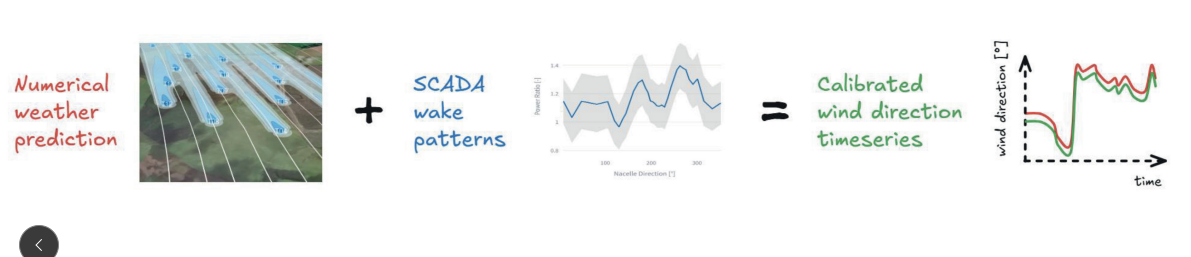
Wind direction offset calibration
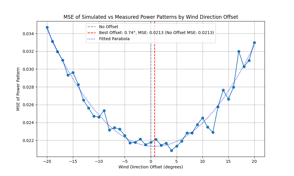
The wind direction simulated by the model can deviate from the true wind direction by several degrees. The offset is calibrated by comparing the wake patterns observed in SCADA data with those predicted by the wake model. The simulated wind direction is shifted until the two patterns are optimally aligned.